Ivoprop - Ivo prop - Ivo propeller
1-800-FOR-PROP
Ivoprop service bulletins
Subject:
Ivoprop ultralight & model 3:1 gearboxes or direct drive engines or 3
cylinder engines. Note This Service Bulletin supersedes any previous
operational alerts issued by Ivoprop Corp.
Purpose:
To detect blade
movement inside the hub due to improper installation and, or harmonic resonance
between prop and power plant; To prevent further flight if this situation
is detected and develops in unsafe condition (aluminium bushings becoming
loose breaking bolts, blades etc ... ) "new blades do not have
bushings"
Introduction:
Above mentioned
combinations produce high level of torsional pulses during their firing
cycle which several times exceed their nominal torque and also torque
reversal pulses. If the prop is mounted loose and or gets in harmonic
resonance with the engine the blades could move inside the hub back and
forth in a plane of prop rotation.
What
to do: Prior to the
next flight, accomplish the following:
Get
torque wrench and check its calibration by hanging a known weight on its
arm and multiplying the weight in pounds by arm in inches. This reading
should be as close as possible to actual recommended torque on mounting
bolts. (We tried several torque wrenches and most of them were off by a
lot.) Check torque on mounting bolts. 200 inch x lbs.
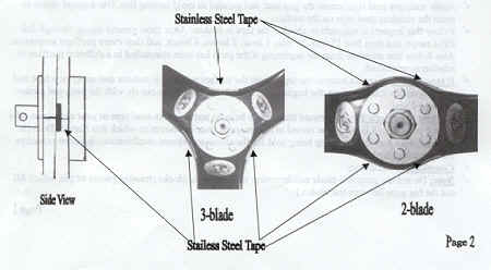
Direct
drive engines only: Mark the prop position in relation to the
crankshaft. There are two positions to mount 3-blade prop and three
positions to mount 2-blade prop; this makes a great difference in how
the
prop and engine vibrate together and each position creates a totally new
situation. It is impossible to determine which position is best for your
particular prop engine airframe combination without actually testing it on
it.
Run
the engine momentarily on the ground trough the full RPM range.
Check
the torque on the mounting bolts and, if you are not using locknuts, safety wire
the bolts.
Cut the strips of stainless steel tape about 2" long and
'/4" wide (tape supplied with this service bulletin) Clean the area
around the gap between blades, or gap between blades and blade blocks with
MEK solvent.
Apply
stainless steel tape across the gap next and parallel to mold parting
line. Use a round object to press the stainless steel tape on the surface.
Follow this inspection schedule to check if the tape is broken:
After short ground run up through full RPM range, and then first 15 min,
30 min, I hour, 2 hours, 4 hours, and then every preflight inspection.
Also follow this schedule from the beginning if the prop has been
reinstalled in a different position in relation to crankshaft.
If
tape breaks or
cracks remove the tape, clean the surface with MEK solvent and apply new
tape and start inspection schedule from the beginning. If tape breaks
again, do not fly with the prop and contact Ivoprop Corp.
Request
to dealers: Please forward
this service bulletin and stainless steel tape to your customers who are
subject to this S.B. Keep the record of addresses of your customers to
which this Service Bulletin applies. Make sure that any prop being sold
for the above-mentioned combinations is accompanied by this Service
Bulletin.
Compliance:
Mandatory
Note:
Do not use prop in 2-blade configuration without blade blocks
(missing
pieces of pie, which fill out the big gaps between the blades.)
Ways your prop can come loose!
Not
torquing the bolts
Do not rely on feel. Get torque wrench and calibrate it by yourself.
Torque on mounting bolts is 200 inch x lbs. ( not 200 ft x lbs.)
Bottoming
the thread of the mounting bolts into the flange or lock nuts. Use
extra washers if the bolts are too long.
Inserting
spinner composite baking plate anywhere between what bolts is supposed
to compress together.
These fiberglass or composite backing plates compress with heat and
pressure resulting in torque loss on the bolts.
Using
wrong hardware.
Rotax engines are supplied with prop crush plate which has stamped
oversized holes. Do not use it.
Important
:
Do
not modify the prop in any way.
Do
not weld super cams on torsional rod.
Direct drive engine adaptors need AN5 bolts not 8mm bolts.
Knurled Plates Instructions - Ultralight Model
The knurled
plates should be installed so that knurling finish on each plate is in
contact, with blades.
The knurled
pattern is 60 degrees symmetrical so, if you re-install the blades between
crush plates later in a different position, the imprint on the blades
should match the knurled pattern. However, due to manufacturing
tolerances, to get the best match, number the blades and plates and always
put the blades back in the same place.
Torque the
mounting bolts to 200 inch x lbs. Dry (no oil or
lubricant the thread) and run the prop momentarily through full RPM range.
Re-torque the bolts.
Install the
Service Bulletin stainless steel tape and follow the inspection schedule
from the Service Bulletin. Any time you inspect the tape, check the torque
on the bolts during first four hours. After that, check torque every ten
hours.
If your blades have aluminum bushings around the bolt holes, make sure that knurled plates supplied to you are counter bored around the bolt holes.
If you require further information email us at:ivoprop@gmail.com

IVOPROP
CORP
2615 East 67th St. Unit E
Long Beach, CA 90805
562-602-1451
ivoprop@gmail.com
1-800-FOR-PROP